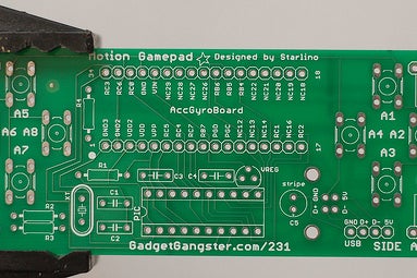
Play your favorite PC, Mac, or Linux games just by tilting! The Motion Gamepad translates your movements into in-game actions, like turning a steering wheel or throwing a ball. An advanced interface makes it easy to customize, and a 3-Axis, 2kHz accelerometer gives you super smooth and accurate control.
It’s a perfect fit on the Wii Wheel, but you can mount it on just about anything. Why not put it on a helmet or your arm or leg?
Step 1: FAQ
How is this different than a Wiimote?
The Motion Controller is similar, but improves on the wiimote in a few key areas;
- USB Connection: your computer doesn’t need bluetooth, and there are no batteries to run out.
- Multiple OS Support: uses standard USB HID protocol, so no drivers are necessary.
- Software Upgradeable: upgrading the Motion Controller firmware is easy via USB.
- Higher Quality Sensor: the accelerometer used (ST LIS331AL) has a significantly higher sampling bandwidth for more accurate and more responsive gameplay.
- Hackable: buttons can be easily mounted on a case, on a steering wheel, or anywhere else you prefer. Configuration utility lets you further customize your controller to fit your exact preferences.
Does it work with Mac, Linux, or OS/2 Warp?
If your operating system supports the USB Keyboards, it should work fine with the Motion Controller. That includes all modern operating systems like Windows, OS X and Linux.
Is there any Surface Mount Soldering?
Nope! Accelerometers are only available as surface mount devices, but the Motion Controller uses an accelerometer breakout board (The Acc_Gyro) that comes pre-assembled.
Where can I mount it?
It was designed to be easiest to mount into an official or generic Wii wheel, and the pin headers act as prongs to lock the Motion Gamepad in firmly, but it can be mounted into nearly anything, and mounting holes are drilled on the board.
The Motion Gamepad and Acc_Gyro Board were designed by Starlino. The Motion Gamepad is available as a kit from Gadget Gangster.
Step 2: Preperation: Tools
The Motion Gamepad takes about 30 minutes to put together. Soldering is straightforward, and it’s a fine project if you’re just starting out. There are a ton of great instructables on how to solder (one here).
Tools
You’ll need a few tools to assemble the project;
1 – Soldering Iron and solder. Leaded solder is easier to work with, and a 15-40 watt iron is just fine. A conical or chisel tip works well.
2 – Dikes. Diagonal cutters are used to trim the excess leads from components after soldering them down.
Step 3: Preperation: Parts
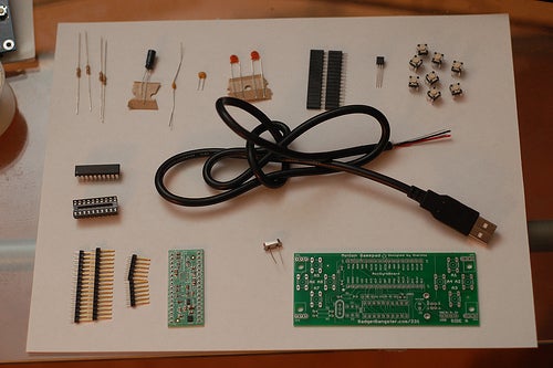
Here are the parts you’ll need. If you’ve ordered a kit, double check to make sure your package has all the parts listed. If there’s anything missing, just email us at [email protected];
Motion Gamepad PCB
Source: Gadget Gangster
Qty: 1
PIC18F14K50
Mouser Part #: 579-PIC18F14K50-I/P
Qty: 1
If you get this with the kit, it will come pre-programmed (and can be upgraded via usb). Otherwise, you’ll need a PICkit to program it.
10k ohm Resistor
Marked: Brown – Black – Orange
Qty: 4
.47uF Radial Ceramic Capacitor
Marked: 474
Mouser Part #: 80-C320C474M5U
Qty: 1
.1uF Axial Ceramic Capacitor
Marked: 104
Mouser Part #: 80-C410C104K5R-TR
Qty: 1
18pf Radial Ceramic Capacitor
Marked: 18
Mouser Part #: 140-50N5-180J-TB-RC
Qty: 2
10uF Radial Electrolytic Capacitor
Mouser Part#: 647-UVR1V100MDD1TD
Qty: 1
12Mhz Crystal
Size: HC49/U-S
Mouser Part#: 815-ABL-12-B2
Qty: 1
Omron Switches
Size: 4.3mm
Mouser Part#: 653-B3F-1000
Qty: 8
20 Pin DIP Socket
Mouser Part#: 517-4820-3004-CP
Qty: 1
Pin Headers
Qty: 49
Pin Sockets
Qty: 34
AccGyro Board
Source: Gadget Gangster
Qty: 1
USB A Plug – Wire Cable
Qty: 1
Voltage Regulator
MCP1700 (5V, TO-92)
Mouser Part#: 579-MCP1700-3302E/TO
Qty: 1
Step 4: Make: Step I
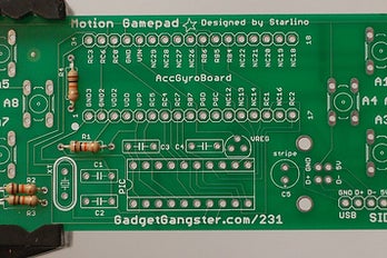
There are 4 resistors in the project, they’re all identical (10k ohm – Brown – Black – Orange) and they go on the board at R1, R2, R3, and R4.
Bend the leads at a 90 degree angle, and insert them in the board. Flip over the board, solder them down, and trim off the excess leads.
Step 5: Make: Step II
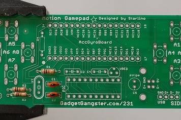
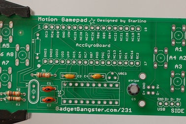
Let’s add the capacitors.
The Orange disc shaped caps should have an ’18’ marked on them. Those caps go at C1 and C2. These caps are not polarity sensitive, so it doesn’t matter which way you insert them.
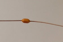
There’s a .1uF axial ceramic capacitor, it goes at C4. Axial means the wires come out the ends – like a resistor. You might be able to see the marking on the body of this one – it’s ‘104’. It is also not polarity sensitive.
C3 is the last ceramic capacitor. it’s .47uF, you can verify you’ve got the right one by checking the marking on the body, it should have the number ‘474’. It’s also not polarity sensitive.
Now for the final capacitor, it’s an electrolytic capacitor and it goes in C5. The value is 10uF, and it is polarized. The stripe on the body of the component should go closer to the word ‘stripe’ on the circuit board.
Step 6: Make: Step III
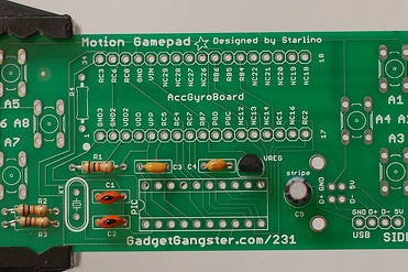
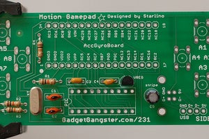
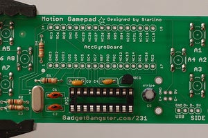
Let’s add the voltage regulator, it’s shaped like a cylinder cut in half, it goes on the board at ‘VREG’. Note how the marking on the board has a flat side pointing down – the regulator should go in the board also having the flat side point down.
The Crystal goes at XT. The crystal is not polarized, so it doesn’t matter which lead goes in which hole.
Now for the buttons;
The most common way of adding the buttons is directly on the board. To do this, just flip the pcb over and snap them in. Flip the board back and solder them down.
If you want to install the buttons somewhere else (like on the top of a steering wheel), use a bit of hookup wire to connect the button to the hole it would normally go in.
Finally, add the DIP socket on the board at the spot marked ‘PIC’. Note that the notch on the socket should point left (closer to the word ‘PIC’).
Step 7: Make: Step IV
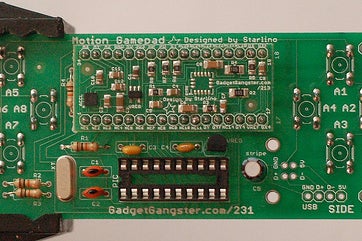
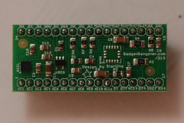
The accelerometer is on a separate breakout board (the Acc_Gyro Board, Accelerometer Only) because accelerometers only come in surface mount packages and are pretty difficult to solder by hand, so this part comes pre-assembled. All you have to do is add pin headers.
To Socket or Not To Socket
The kit also comes with pin sockets – you can add pin sockets to the Motion Gamepad PCB at the area labeled ‘AccGyro’ and slide the Acc_Gyro Board into the socket. The advantage of using sockets is that you’ll be able to remove the Acc_Gyro Board and use it for other projects.
Personally, I found it easier to forgo using sockets. I just soldered the pin headers straight to the board and cut off the extra length of pin headers on the other side. I won’t be able to re-use the accelerometer on other projects, though.
Step 8: Make: Step V
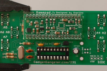
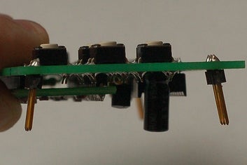
Add 3 pin headers at each corner of the board (JP1, JP2, JP3, and JP4). When you solder them down, it’s best to ‘splay’ them apart (see 2nd photo). These headers will hold the PCB to the Wii wheel. You can also use pliers (or dikes) to bend them out further.
Step 9: Make: Step VI
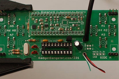
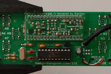
Almost finished! Let’s add the USB Cable;
Trim off the outer rubber jacket and excess shielding from the USB Cable. You’ll see 4 wires inside the cable. You’ll want to expose about 6″ of those wires – strip the conductor and tin the leads of each.
Run them in the top hole and back through the bottom hole, as shown in the image. Once they’re through, you’ll connect each wire to the board;
Black: GND
Green: D+
White: D-
Red: 5V
Lastly, put the PIC in the socket – note the notch points to the left.
Step 10: Other Mounting Ideas
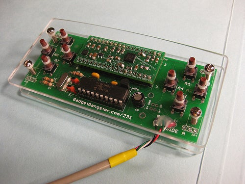
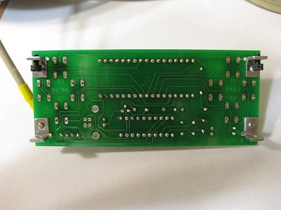
The easiest way to mount the Gamepad is in a Wii Wheel. The pin headers on the corner of the pcb can be bent to firmly grab on to a genuine Wii Wheel, or a generic one. You can also put it in any other enclosure – there are 4 mounting holes to help you. Check the photos below for a few ideas on mounting
Step 11: The Acc_Gyro Board
The Acc_Gyro Board is a core part of the Motion Gamepad and contains the Accelerometer that reads movement. It’s socketed, so if you’re into programming microcontrollers like Arduino or Propeller, you can use it in your own projects.
An enhanced version of the Acc_Gyro is available separately – it adds a Gyroscope to give a 5DOF Inertial Measurement Unit (IMU) with 5V and 3V capability. There’s a ton more info on using the Acc_Gyro here. Full pinout information is available in PDF format, but to summarize:
P13: GYF, Gyro non-amplified, filtered Y-axis Output
P15: GY4, Gyro amplified (x4), Y-axis Output
P16: VREF, Gyro Reference Voltage (1.25V, fixed)
P17: GX4, Gyro amplified (x4), X-axis Output
P18: GXF, Gyro non-amplified, filtered X-axis Output
P26: ST, Gyro self test (logic 0 = normal, 1 = self test mode)
P27: PD, Gyro power down (logic 0 = normal, 1 = power down mode)
P28: HP, Gyro high pass filter reset (logic 0 = normal, 1 = Reset HP filter)
P29: 3V3, Voltage regulator output (3.3v)
P30: Supply Voltage input, 5v
P31: GND, Ground
P32: AZ, Accelerometer Z-axis analog filtered output
P33: AY, Accelerometer Y-axis analog filtered output
P34: AX, Accelerometer X-axis analog filtered output
Using the Accelerometer

The accelerometer measures acceleration around several axis. If you set the Acc_Gyro board on the table as shown in the photo above, the Z axis will experience 1G and AZ will output 1.17V. The X and Y axis’ don’t have gravity pulling on them, they’re at 0G, and will output 1.65V.
If you put it on the table upside down, the X and Y axis’ would still have 0G of acceleration, so you’d get AX = 1.65V, AY = 1.65V, and AZ = 2.13V. The Acc_Gyro board is capable of measuring accelerations of +/-2G (+/-19.6m/s^2) along any axis. 2G is the same as going from 0 to 44mph in 1 second. When an axis experiences +2G, it will increase voltage to 2.6V. When it experiences -2G, it will decrease voltage to .7V.
Please note that gravitation force (directed from sky to ground) has same effect on the device as if you would accelerate the device in an opposite direction, in a place with no gravitation field. So keep this in mind if you’re planing to use the device for something like measuring the acceleration of your car or bike.
bla
Step 12: Downloads
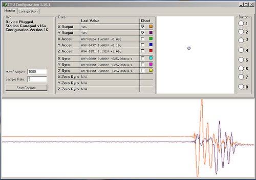
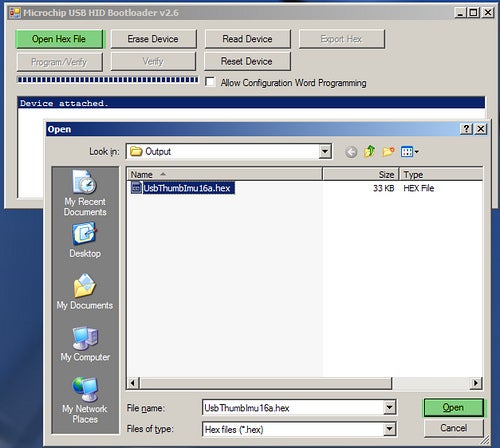
I hope you enjoy the Motion Gamepad! Let me know what you think by commenting on this instructable or sending me an email at [email protected].
Setup
The Motion Gamepad uses standard HID drivers, but you can use the IMU configuration utility (windows) – download here to do an enhanced setup / calibration. Starlino has done a great guide on setting it up with the IMU utility here (pdf).
Software
The HEX for the PIC is here. As a kit, the PIC comes pre-programmed, and the way it’s programmed, you can update the firmware with a little update utility – here.
Design
Here’s the board layout and schematic (eagle format)
Get the kit at Gadget Gangster.


