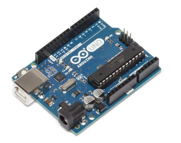
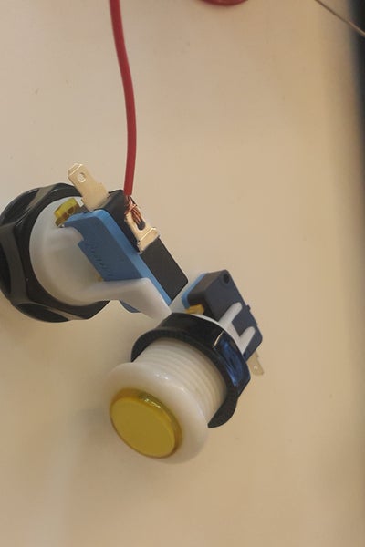
Hi guys, this is my first instructable so please be nice to me. 😉
The goal for this instructable is to implement a door control system for magnet locks using an arduino board. The idea is to have an external button for manual control and a bluetooth app for handheld control. Our requirement is a 5-channel control for 5 different doors but for the case of this instructable, I’ll show you how to make a single-channel control. I’ll also share the 5-channel control later. We initially implemented an online door control using raspberry pi where we used QR codes as keys but we keep having problems with our internet service so we decided to make it a little bit simpler.
Step 1: Materials
Materials I used for this project are the following. I’m sure you can purchase these items from your local electronics shops.
Arduino Uno + USB
8-Channel Mechanical Relay
Arcade buttons
Protoboard/Breadboard
Resistors
Tablet for Android App
Laptop/PC with Arduino IDE
Internet for App Inventor (for the bluetooth app)
HC-06 Bluetooth Module
5-12V Power Supply
Wires and Header pins
Cardboard box for casing
Step 2: Step 1: Doing the Prototype (Buttons)
For the magnetic lock to work, we need to feed in a current from a 5V (max 12V depending on your lock) power supply. This will trigger the electromagnet which in turn will lock the door. For us to be able to control the flow of current, we will use the mechanical relay. You can learn more about mechanical relays from other instructables.
Our first step is to setup a prototype to control the mechanical relay. For the sake of this instructable, i will use a single channel relay, breadboard, and some push button to demonstrate the circuit. Then we’ll expand this to 5-channel control later.
Build the circuit according to the schematic. Two push buttons will serve as the entry and the exit buttons. NOTE: Dont forget to add the resistors to avoid shorting your circuit. I connected the relay to the analog pins of the arduino uno to give way for the remaining buttons which we will connect later using the digital pins. Once you are done, upload the attached code <DoorControlProto.ino>.
//Declare Variables
#define RelayA A1  //connected to the relay signal
#define button1 10 //connected to button 1
#define xbutton1 11 //connected to exit button 1int button1_state = 0; //variable for state of button 1
int xbutton1_state = 0; //variable for state of exit button 1
int duration = 3000; // duration set
unsigned long TimerA; //variable for timingvoid setup()
{
  //declare pinmodes for Relay as OUTPUT, and INPUT for buttons
  pinMode(RelayA,OUTPUT);
  pinMode(button1,INPUT);
  pinMode(xbutton1,INPUT);
  Serial.begin(9600);
}void loop()
{
  //check for the state of each buttons
  button1_state = digitalRead(button1);
  xbutton1_state = digitalRead(xbutton1);  //if any of the buttons are pressed
  if ((button1_state == HIGH) || (xbutton1_state == HIGH))
  {
    //sets the time when the button was pressed
    TimerA = millis(), digitalWrite(RelayA,LOW);
  }
  /*if the difference between the running time
  and the time when button was pressed is greater
  than the duration set*/
  if (millis() - TimerA >= duration)
  {
    digitalWrite(RelayA,HIGH);
  }
}
Attachments
Step 3: Step 3: Building the 5-Channel Relay Controller
Next step is we’ll expand the circuit to control five (5) relay channels. Just do the same thing as the single channel controller. Make sure to take note of the pins for the entrance and exit buttons, and the signal pin of the relay. Use the arcade buttons instead of the little push button. I tried to solder all
Since I need a quick and permanent setup, I used a protoboard and soldered header pins for +5V pins, GND, and button pins. You can do the same or make your own PCB, that’s all up to you. I also used a spare box for my button case. The box is big enough to house the protoboard and the arduino board inside but you can use any case that you want.
With that, we now have a working controller. You just have to connect the magnet locks to the relay and you’re good to go.
I’m sharing with you the arduino code, in case you need the 5-channel version:
//Project: 5-Channel Door Control System
//Author: Art Galapon
//Date Completed: 02/17/2017//Variable Declaration#define RelayA A5
#define RelayB A4
#define RelayC A3
#define RelayD A2
#define RelayE A1#define button1 3
#define button2 4
#define button3 5
#define button4 6
#define button5 7#define xbutton1 9
#define xbutton2 10
#define xbutton3 12
#define xbutton4 11
#define xbutton5 8 int xbutton1_state = 0;
int xbutton2_state = 0;
int xbutton3_state = 0;
int xbutton4_state = 0;
int xbutton5_state = 0;int button1_state = 0;
int button2_state = 0;
int button3_state = 0;
int button4_state = 0;
int button5_state = 0;int duration = 3000;
unsigned long TimerA;
unsigned long TimerB;
unsigned long TimerC;
unsigned long TimerD;
unsigned long TimerE;byte state = 0;void setup() {
 //Pin mode declaration

  pinMode(RelayA,OUTPUT);
  pinMode(RelayB,OUTPUT);
  pinMode(RelayC,OUTPUT);
  pinMode(RelayD,OUTPUT);
  pinMode(RelayE,OUTPUT);

  pinMode(button1,INPUT);
  pinMode(button2,INPUT);
  pinMode(button3,INPUT);
  pinMode(button4,INPUT);
  pinMode(button5,INPUT);  pinMode(xbutton1,INPUT);
  pinMode(xbutton2,INPUT);
  pinMode(xbutton3,INPUT);
  pinMode(xbutton4,INPUT);
  pinMode(xbutton5,INPUT);

  Serial.begin(9600);
}void loop() {
//Reads the state of server buttons located in the server area
 button1_state = digitalRead(button1);
 button2_state = digitalRead(button2);
 button3_state = digitalRead(button3);
 button4_state = digitalRead(button4);
 button5_state = digitalRead(button5);//Reads the state of exit buttons within each room
 xbutton1_state = digitalRead(xbutton1);
 xbutton2_state = digitalRead(xbutton2);
 xbutton3_state = digitalRead(xbutton3);
 xbutton4_state = digitalRead(xbutton4);
 xbutton5_state = digitalRead(xbutton5); /*Checks for bluetooth connection. If there's a connection, it will
 read any data sent and will store in variable state*/

 if (Serial.available() > 0)
 {
  state = Serial.read();
  Serial.println(state);
 }//Door Execution

  if ((button1_state == HIGH) || (xbutton1_state == HIGH) || (state == 52))
  {
    TimerA = millis(),digitalWrite(RelayA,HIGH);
    state = 0;
  }
  if (millis() - TimerA >= duration)
  {
    digitalWrite(RelayA,LOW);
  } if ((button2_state == HIGH) || (xbutton2_state == HIGH) || (state == 51))
  {
    TimerB = millis(), digitalWrite(RelayB,HIGH);
    state = 0;
  }
  if (millis() - TimerB >= duration)
  {
    digitalWrite(RelayB,LOW);
  } if ((button3_state == HIGH) || (xbutton3_state == HIGH) || (state == 49))
  {
    TimerC = millis(), digitalWrite(RelayC,HIGH);
    state = 0;
  }
  if (millis() - TimerC >= duration)
  {
    digitalWrite(RelayC,LOW);
  } if ((button4_state == HIGH) || (xbutton4_state == HIGH) || (state == 50))
  {
    TimerD = millis(), digitalWrite(RelayD,HIGH);
    state = 0;
  }
  if (millis() - TimerD >= duration)
  {
    digitalWrite(RelayD,LOW);
  } if ((button5_state == HIGH) || (xbutton5_state == HIGH) || (state == 53))
  {
    TimerE = millis(), digitalWrite(RelayE,HIGH);
    state = 0;
  }
  if (millis() - TimerE >= duration)
  {
    digitalWrite(RelayE,LOW);
  }
}
Attachments
Step 4: Step 4: Bluetooth Control and App (Optional)
The next steps are optional but a cool, if not great, addition to the system. I added a bluetooth module (HC06) to the system.
Connect HC06 to Arduino following this pin connection:
HC06 >> Arduino Uno
GND >> GND
Vcc >> +5V
RX >> TX (D1)
TX >> RX (D0)
With this, we will add some lines in the code. This is already in the attached 5ChannelControl arduino file so no need to edit it if you’re using the same ino file. We added an extra conditional using OR (||) for the bluetooth control. You can use any bluetooth app like Bluetooth Control or Arduino BlueControl for android. You also have the option to make your own app using App Inventor.
//Project: 5-Channel Door Control System
//Author: Art Galapon
//Date Completed: 02/17/2017//Variable Declarationbyte state = 0;void loop() {
 /*Checks for bluetooth connection. If there's a connection, it will
 read any data sent and will store in variable state*/

 if (Serial.available() > 0)
 {
  state = Serial.read();
  Serial.println(state);
 }//Door Execution
  if ((button1_state == HIGH) || (xbutton1_state == HIGH) || (state == 1))
  {
    TimerA = millis(),digitalWrite(RelayA,HIGH);
    state = 0;
  }
  if (millis() - TimerA >= duration)
  {
    digitalWrite(RelayA,LOW);
  } if ((button2_state == HIGH) || (xbutton2_state == HIGH) || (state == 2))
  {
    TimerB = millis(), digitalWrite(RelayB,HIGH);
    state = 0;
  }
  if (millis() - TimerB >= duration)
  {
    digitalWrite(RelayB,LOW);
  } if ((button3_state == HIGH) || (xbutton3_state == HIGH) || (state == 3))
  {
    TimerC = millis(), digitalWrite(RelayC,HIGH);
    state = 0;
  }
  if (millis() - TimerC >= duration)
  {
    digitalWrite(RelayC,LOW);
  } if ((button4_state == HIGH) || (xbutton4_state == HIGH) || (state == 4))
  {
    TimerD = millis(), digitalWrite(RelayD,HIGH);
    state = 0;
  }
  if (millis() - TimerD >= duration)
  {
    digitalWrite(RelayD,LOW);
  } if ((button5_state == HIGH) || (xbutton5_state == HIGH) || (state == 5))
  {
    TimerE = millis(), digitalWrite(RelayE,HIGH);
    state = 0;
  }
  if (millis() - TimerE >= duration)
  {
    digitalWrite(RelayE,LOW);
  }
}


