It feels awesome when you have the power to control things remotely.
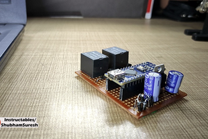
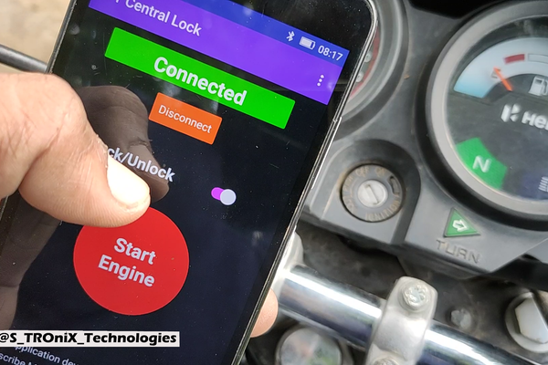
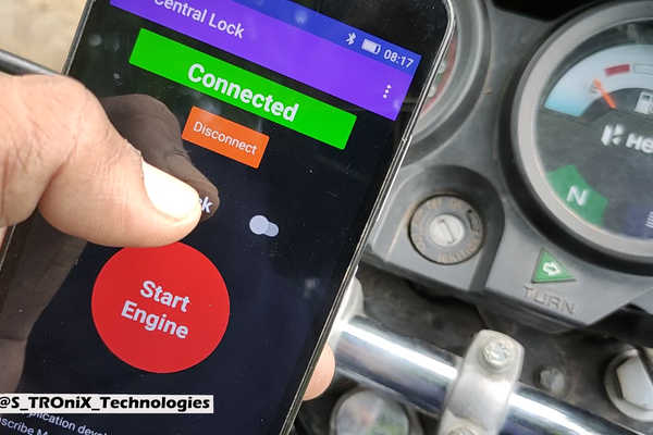
Smart Central lock device for motorcycle (bike). by using this device you can control your bikes ignition lock. you can Lock/ unlock it remotely. Also can start and stop the engine by using your smartphone. So let’s see how you can make one by yourself.
Step 1:

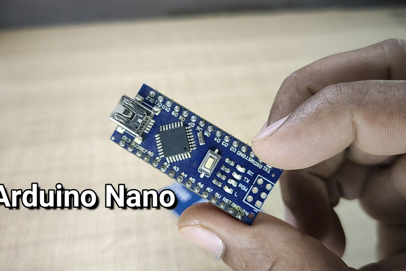
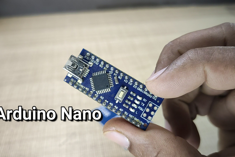
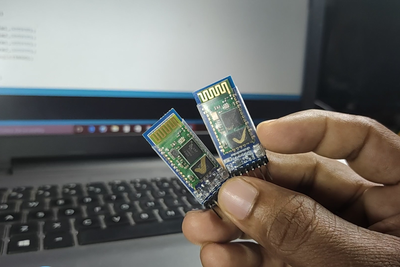
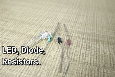
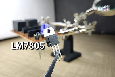
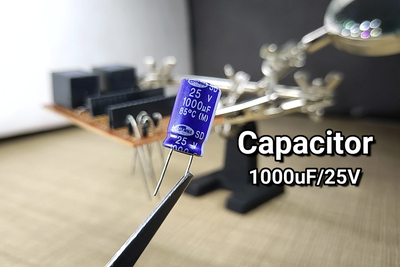
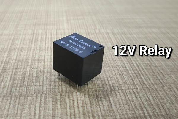
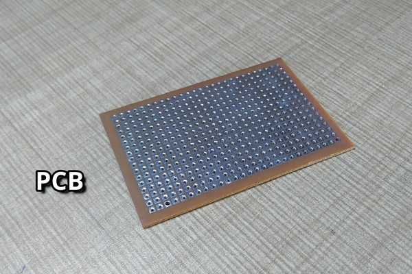
You need all the above mentions components to make this device.
Components Used: …………………………………………………..Buy Links
1- Arduino nano X1…………………………………………………. USA / INDIA
2- Bluetooth Module X1……………………………………………. USA / INDIA
3- 12V Relay X2………………………………………………………. USA / INDIA
4- Capacitor 1000uF/25V X2……………………………………… USA / INDIA
5- 1K Resistors X2 …………………………………………………… USA / INDIA
6- Diodes 1N4007 X6……………………………………………….. USA / INDIA
7- LM7805 X1 …………………………………………………………. USA / INDIA
8- Transistors BC547 X2 ………………………………………….. USA / INDIA
9- PCB X1………………………………………………………………. USA / INDIA
Step 2:

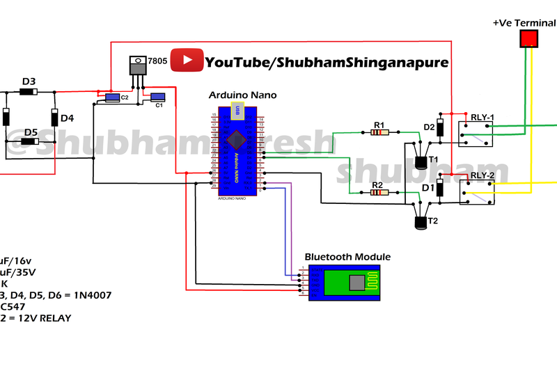
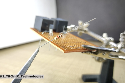
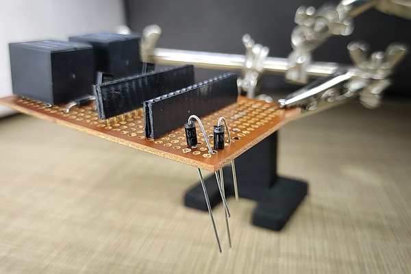
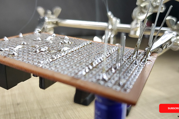
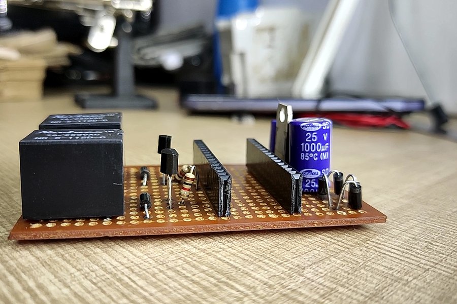
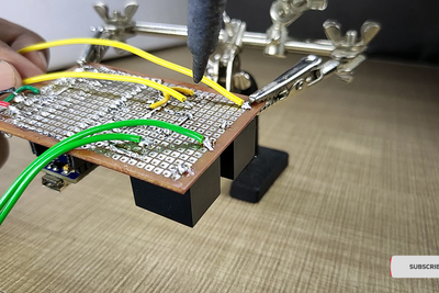
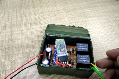
now first solder all the components as per the circuit diagram on a prototype PCB. or you can design custom PCB as per the given circuit diagram. I recommend PCBWay.com for your prototype PCB fabrication.
Circuit Details:
Let’s understand the circuit. starts from the input power supply. it needs 12volt DC power supply to operate. I added a Diode Bridge here to protect this circuit from reverse polarity. after that bridge, I Stepped down the voltage into 5 volts by using a linear voltage regulator IC LM7805. then its feed to Arduino nano and to the Bluetooth module. Bluetooth module connected with Arduino using Tx & Rx pins As Bluetooth’s Tx pin goes to Arduino’s Rx pin And Bluetooth’s Rx pin goes to Arduino’s Tx pin. transistor T1 And T2 Acting As Switch To control the Relay RLY1 & RLY2 respectively. the base of the transistor T1 is connected with the digital pin 5 of Arduino through a current limiting resistor of 1k. and the base of T2 is connected to digital pin 4 of Arduino.
Step 3:
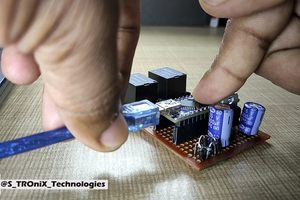
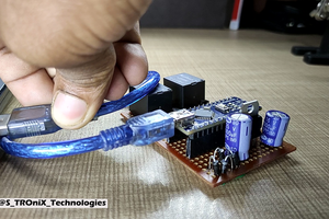
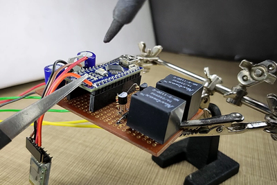
After soldering All components. insert the Arduino nano to it and connect it with PC and upload the given program. Download program and all required Files Here
Step 4:

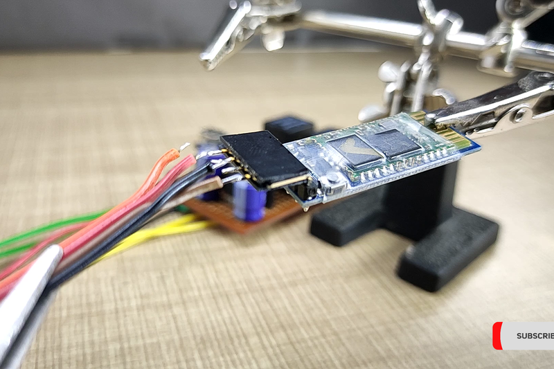
now connect the Bluetooth module with the circuit.
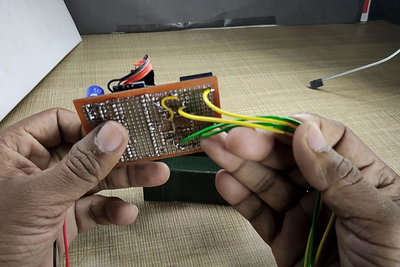
and solder all other wires For power input and to the output pins of the relay for starter and ignition control of the bike. and fit this all circuit assembly inside of an encloser box and close it. I am using a box made up from cardboard.
Step 5:

now its time to install it on a motorcycle. I installing it into my Hero Splendor Plus bike. the wiring diagram provided with this tutorial is tested with only Hero Splendor Plus, Hero Splendor Pro, Hero CD Delux. I am not sure if this wiring work with other bikes. to install it on other bikes rather than above mentioned you need to find out a starter relay of bike and pinouts of it. as well the ignition switch wiring of that bike on which you wish to install this device.
Let, s See how to install it on Hero Splendor Plus.
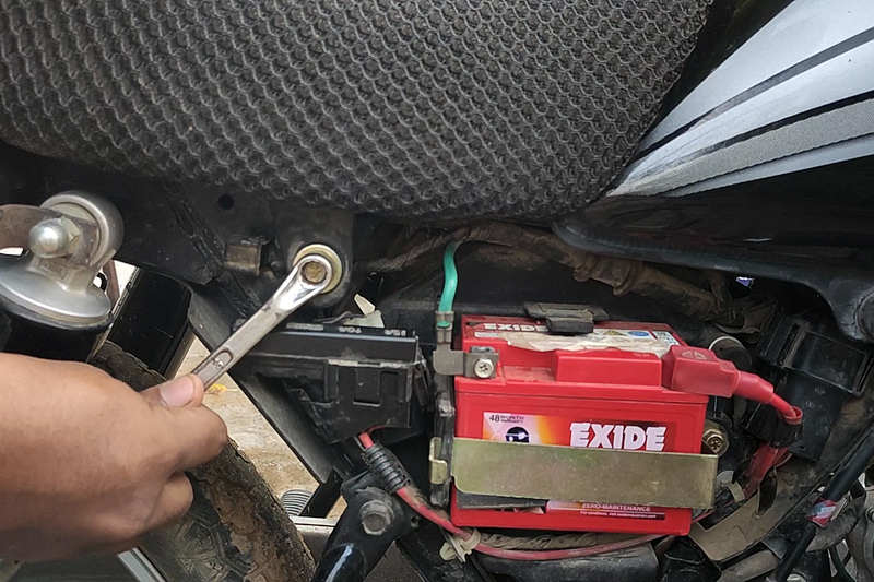
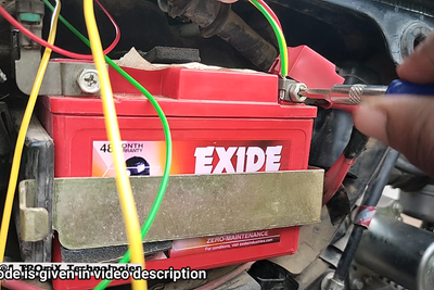
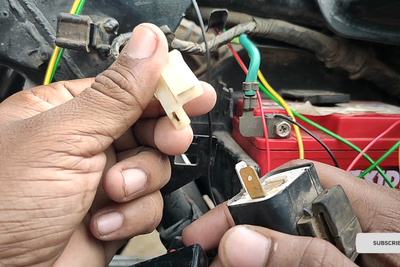
Open battery cover And Seat. and put this device in a suitable position where you find enough space for it. now combine yellow, Green and Red wire and connect them to the positive terminal of the battery. find the flasher relay. it is usually placed near to the battery bellow seat.
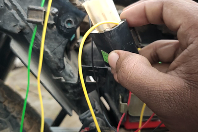
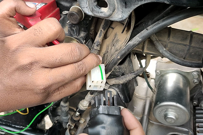
grab that 2 terminal relay and disconnect it from its wire harness. now connect ignition relay wire from our device that is yellow wire to the positive terminal of this connector. now a question arises here, that how to find out which one is the positive terminal? so to find out that take a piece of wire connect it’s one end to the positive terminal of the battery and touch the other end of the wire to both ends of the relay harness. The ignition will be on when the second end of the wire is at any one terminal of the relay harness. The point at which the ignition is on is the positive point of the relay. now connect the yellow wire to that point and put back the flasher relay.
now connect the starter relay wire. for that search for start relay. in my case, it is placed under the fule tank. just remove it and find out the positive terminal of this relay also. now to find out this take a 12volt bulb attach one end of bulb to the negative terminal of the battery and second end of it to one of the ends of start relay harness. and press start button of bike. remember that while testing this you should have to turn on ignition using your keys. now on which point of relay harness bulb will glow that is the target point. now connect green wire into that point and insert back the start relay. and fix it on its position. now all done.
note: if you are not familiar with bike/motorcycle wirings please don’t try it without the help of any bike mechanic. wrong wiring can burn your bike.
Step 6:

i
nstall the application from the given link. click here
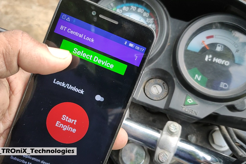
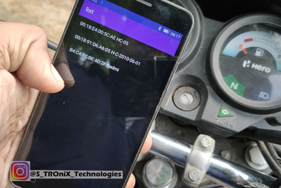
Turn on Bluetooth, search for new device, click on HC-05. enter 1234/0000 if it asks for a password. 1234/0000 is the default password for HC-05, you can change this password by changing its setting. to know more about the Bluetooth module setting visit my previous tutorial. if you still not understand how to change that setting let me know in the comment box and I will make a short note on how to change the Bluetooth setting.
once you connected with device you are ready to operate Lock/Unlock ignition by sliding the switch on the app.

