https://www.youtube.com/watch?v=thTuBdkM_OU
Making an Arduino robot car project is very fun, especially if you make it yourself and are supported by tutorials and tools that support quite complete.
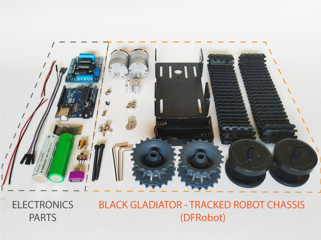
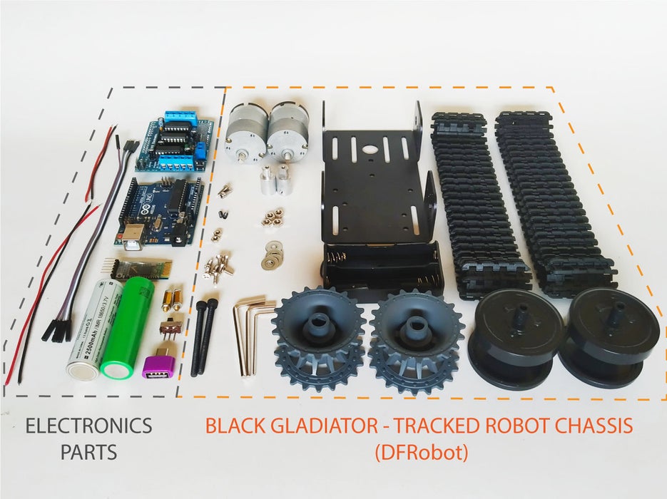
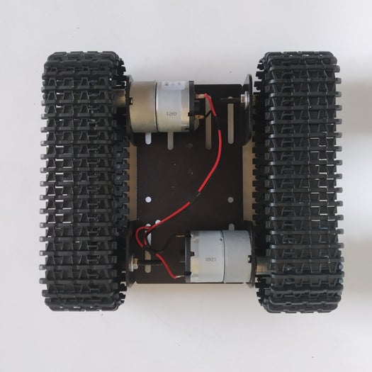
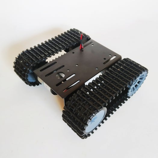
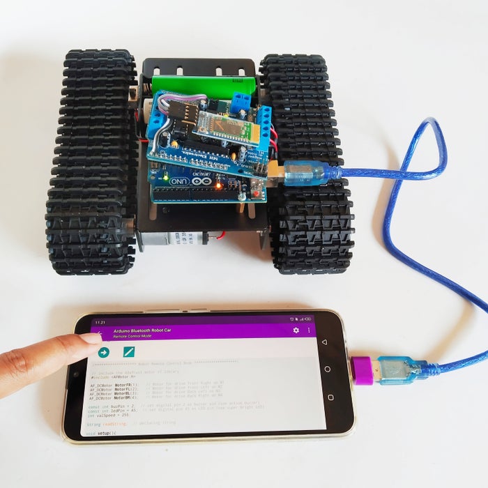
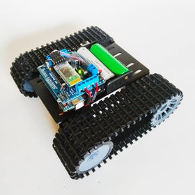
This time we made the Arduino robot car main chassis is powered by the Black Gladiator tracked robot chassis, low noise, and easy to control, which could be a good partner for your tank-liked robots. This tracked chassis employs high-strength aluminum alloy base with delicate appearance, higher stability and longer durability.
Here are tutorials and videos that will guide you from beginning to end with an easy step of course.
Let’s get started!
Step 1: Part Requeriments
- Black Gladiator – Tracked Robot Chassis (DFRobot)
- Arduino Uno
- Motor Shield Adafruit v1
- Bluetooth module HC-05
- Slide switch SPDT
- 4 Female Dupont cable 20cm
- 2 x Cable AWG24 18cm
- 2 x Cable AWG24 14cm
- 2 x Battery 18650 Li-ion 3.7V
- 2 x Spacers 10mm
- OTG adapter
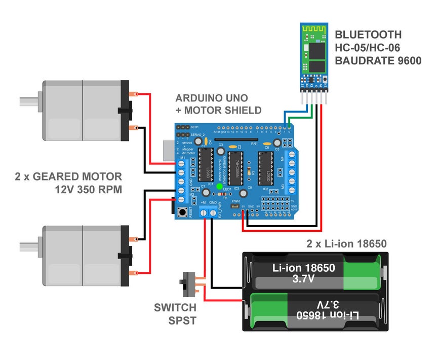
Step 2: Circuit Diagram
Step 3: Mount the Motors
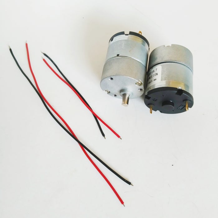
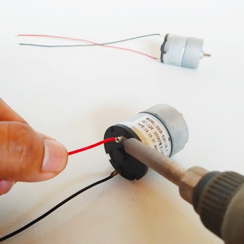
After soldering, you can use heat shrink tube onto the wire so that it covers and secure them futher. It also makes the wires easier to manage.
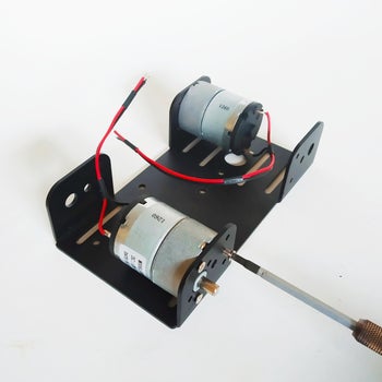
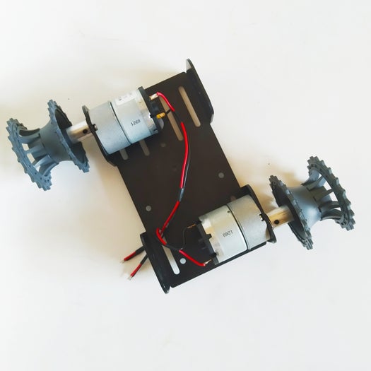
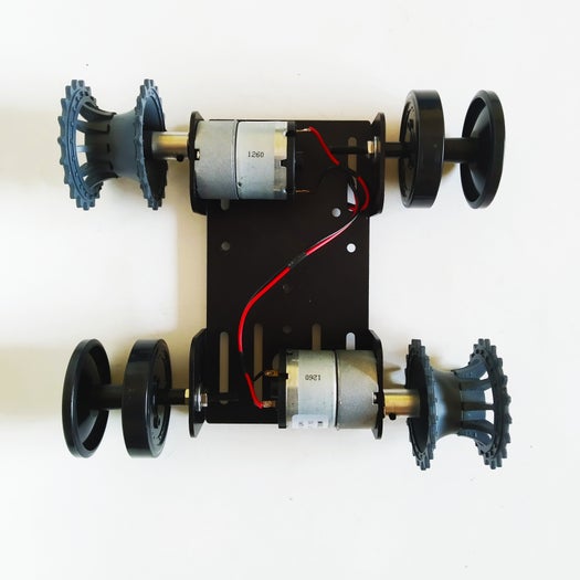
Mount the Motors into metal body chassis and tighten it with 3 M3*6 flat head screws.
Step 4: Install the Drive Wheel

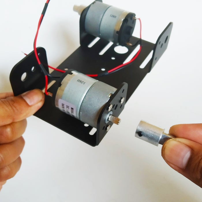
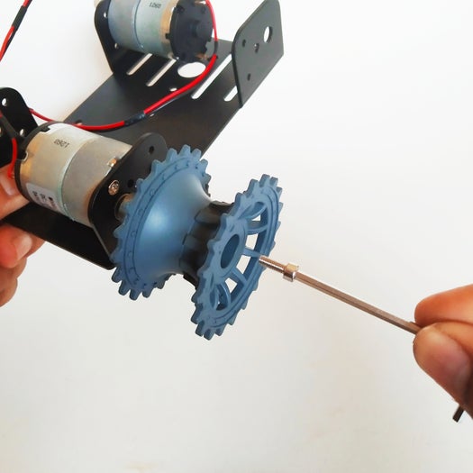
Firstly insert the coupling into shaft of motor and tighten with black screw; please note: the hole on the coupling must be aligned with the flat end of the motor shaft.
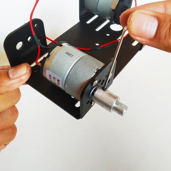
Install drive wheel into coupling, use the allen key to fit the M3*8 hex socket screw into the drive wheel and lock it with the coupling.
Repeat these steps to install the drive wheel on the other side.
Step 5: Install Slave Wheel

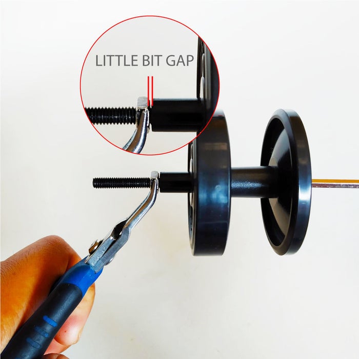
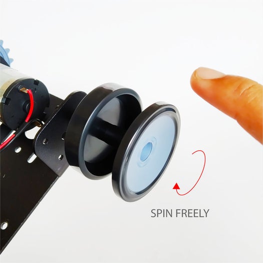
First insert the M4*50 long screw into the slave wheel, and lock the other side with the M4 hex nut. Please provide a gap between the hex nut and the wheel, intended so that the wheel can rotate freely.
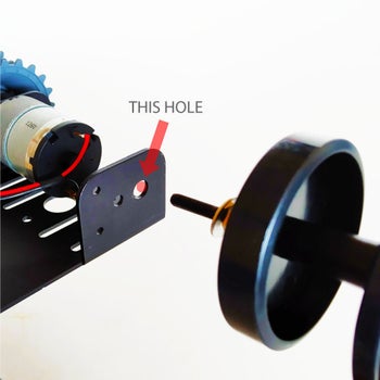
Insert the slave wheel assembly (long screw) to the outer side hole of body chassis, clamped with a ring washer and nut, then tighten it using a pass key or pliers.
When finished make sure the wheels can spin freely.
Repeat these steps to install the slave wheel on the other side.
Step 6: Tracks

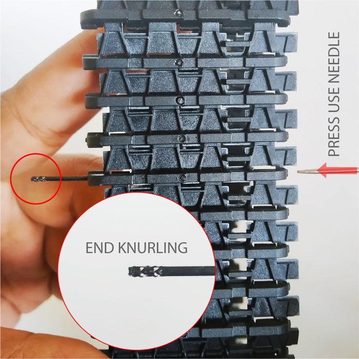
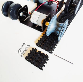
Remove the track first by pressing using the needle, remove the excess part of the track (remove 4 track), and measure the required track length.
Embed the track pin into the track using pliers.
Step 7: Install Battery Holder & Switch

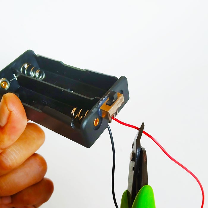
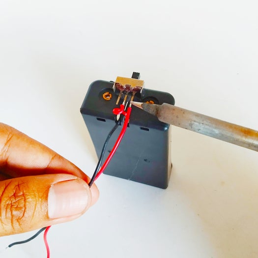
Cut the positive red cable then strip of the insulation off the end of each wire.
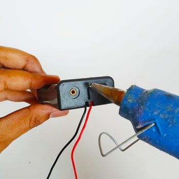
Glue the slide switch SPDT into battery holder.
Solder the positive red cable to two pin of slide switch.
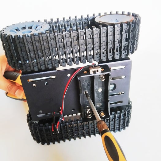
Install battery holder into body metal chassis follow to the existing hole.
Step 8: Install Arduino Board
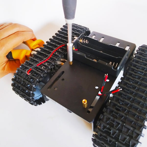
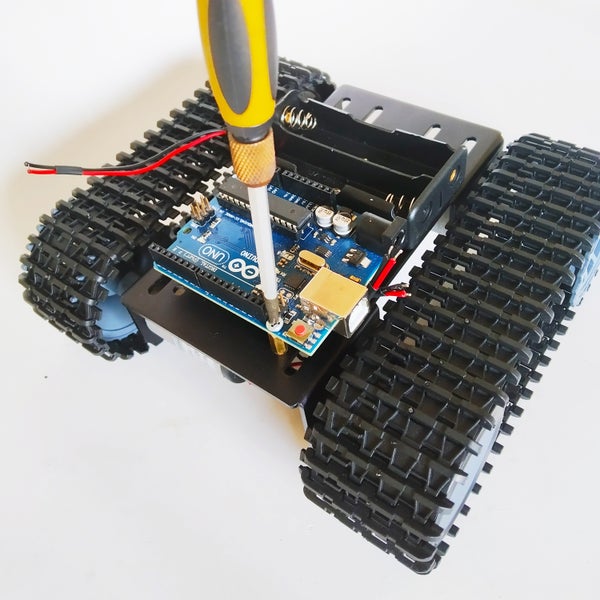
Tighten the two spacer to the holes already in the metal body chassis, then screw the Arduino on them.
Step 9: Add Bluetooth Into Motor Shield

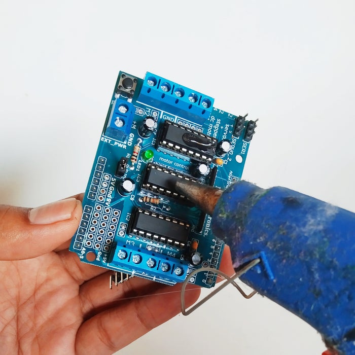
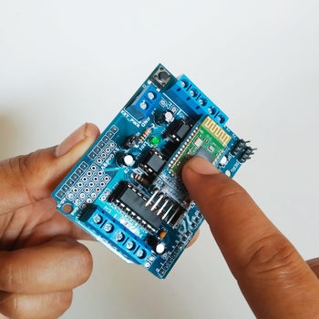
Glue the Bluetooth module HC-05/HC-06 on the top of Motor Shield.
Connect the Dupont cable to pin of HC-05/HC-06, then cut the cable so that it remains about 6cm.
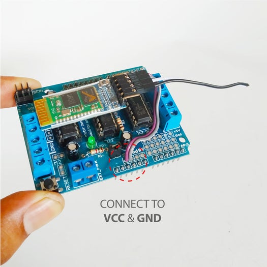
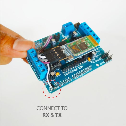
Connect and solder the cable between Bluetooth module HC-05/HC-06 and Motor Shield:
- VCC to 5V
- GND to GND
- RX to D1
- TX to D0
Step 10: Install Motor Shield
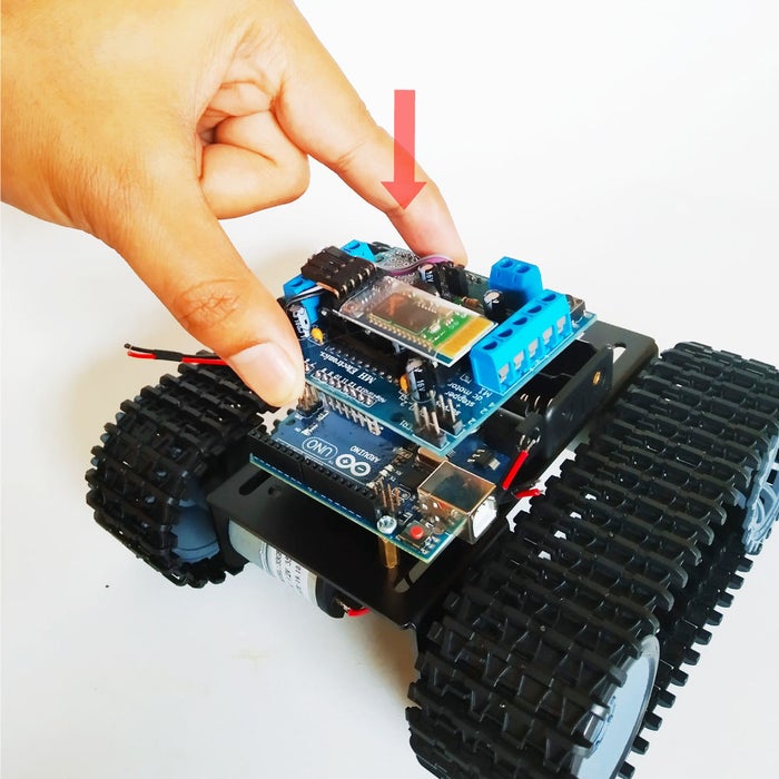
Push the Motor Shield carefully into Arduino, making sure all the pins go into header socket without missing and bending.
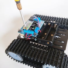
Insert and tighten the motor wires into the respective terminal. Please note: You do not connect the a motor to the two terminals M1 and M2, the correct is the “Right Motor” connect to M1 and the “Left Motor” connect to M2.
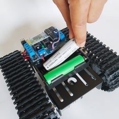
Install two 18650 battery into battery holder.
Step 11: Programming Arduino Board
Last step is programming Arduino Uno board, you can upload code/firmware directly from your Android phone to Arduino Uno via USB OTG. First, get app and instal from Google Playstore the link app is below:
To upload code firmware you need disconnect the pin RX & TX that connected to bluetooth module HC-05/HC-06 or you can do with unplug Motor shield first, this mean to prevent error when process writing code to Arduino through pin D0 & D1 (RX & TX).
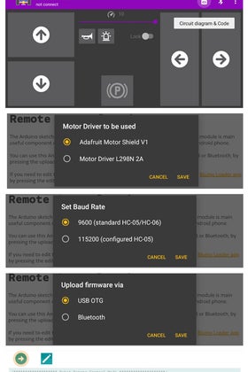
Open the app, then select menu Circuit Diagram & Code, in the Settings menu specify the parameters as follows:
- Motor Driver to be used : Adafruit Motor Shield V1
- Set Baud rate : 9600
- Upload firmware via : USB OTG
Then select Remote Control Mode menu. The last is tap Upload icon and wait moment until the process writing code is completed.
Step 12: Arduino Sketch
If you use computer to upload sketch into Arduino Uno, copy and paste the code bellow to Arduino IDE and upload it.
/******************* Robot Remote Control Mode ********************/

// include the Adafruit motor v1 library
#include <AFMotor.h>

AF_DCMotor MotorFR(1);   // Motor for drive Front Right on M1
AF_DCMotor MotorFL(2);   // Motor for drive Front Left on M2
AF_DCMotor MotorBL(3);   // Motor for drive Back Left on M3
AF_DCMotor MotorBR(4);   // Motor for drive Back Right on M4

const int buzPin = 2;  // set digital pin 2 as buzzer pin (use active buzzer)
const int ledPin = A5;  // set digital pin A5 as LED pin (use super bright LED)
int valSpeed = 255;

String readString;  // declaring string

void setup(){
  Serial.begin(9600);    // set up Serial library at 115200 bps
  Serial.println("*Robot Remote Control Mode*");

  pinMode(buzPin, OUTPUT);  // sets the buzzer pin as an Output
  pinMode(ledPin, OUTPUT);  // sets the LED pin as an Output

  // Set the speed to start, from 0 (off) to 255 (max speed)
  MotorFL.setSpeed(valSpeed);
  MotorFR.setSpeed(valSpeed);

