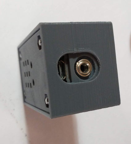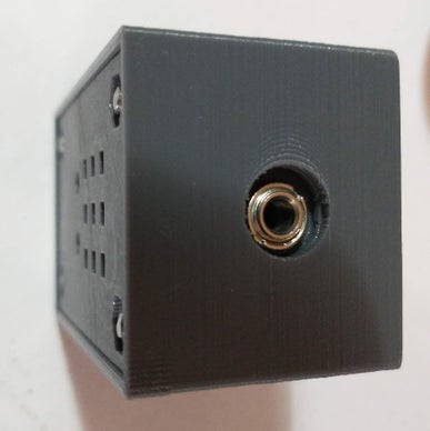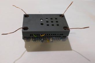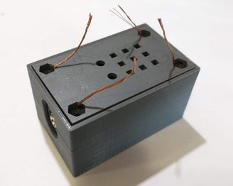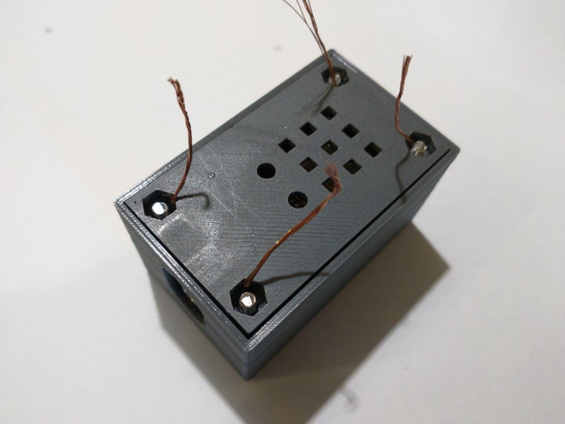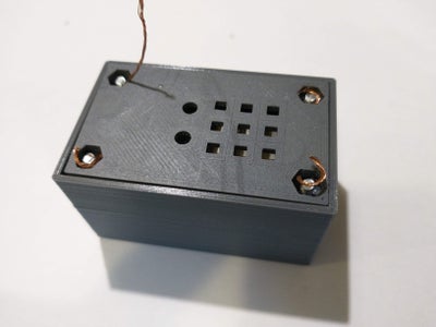
At the beginning it was only a personal challenge. Eventually I like the result. This is the reason I share this desing.
It is smaller than the smaller ones, it is very cheap and easy to build, it is really flexible and strong enough to undergo the hardest conditions.
It has no buttons or potentiometers, so it is really simple to build. The box is 3d printed.
Power supply is 5v USB so it can be powered by a usb power bank. Suitable for portable operation.
Some of its features:
1)-Bluetooth interface. It allows control from mobile phone and other devices.
2)-Up to 25 pre-saved messages (even more, depending of the chosen app) easily written using natural language. Messages are translated automatically to Morse code.
3)-Variable speed from 5 to 70 wpm.
4)-Suitable for paddle key or straight key.
4)-Reverse mode for left-handed operators.
5)-Internal beeper for learning purposes.
6)-Every command is played in Morse code (for blind operators).
7)-It has no push buttons or potentiometers.
8)-3 stored messages in standalone operation. Up to 27 character per message.
9)-Every message could be repeated automatically in a time from 5 to 9999 seg. Repetition stops when touching the paddle/key. Very useful for CQ calling.
10)-Repetition continues after a power supply cut. Useful for beacon operation.
11)-Menu in standalone operation accessible via touch buttons.
12)-Speed control via touch buttons. It plays the final speed in Morse code.
13)-Adjustable touch sensitivity.
14)-Adjustable paddle delay sample.
15)-Tune function. Transmit a continuous carrier for 10 seconds.
Update 06/02/2023 fixed some bug (ESP32_BLUETOOTH_KEYER_STABLE.ino).
Update 25/04/2024 new bluetooth app. The last one is temporary available .
Step 1: 3D PRINTING

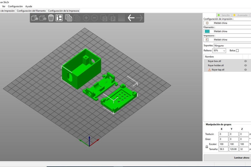
The t
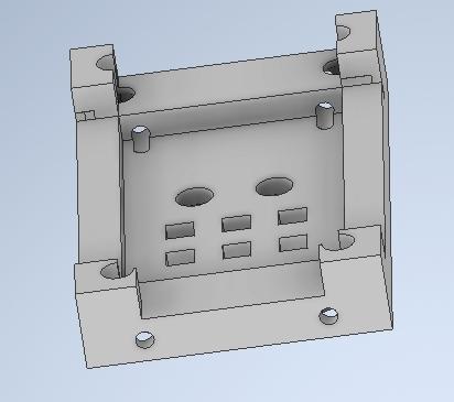
hree parts are designed to be printed without support. The holes are cone-shaped to allow printing without support.
You only have to put them on the bed the way It is shown in picture 1.
I use 4mm nozzle and 0,125 layer height.
Material is PLA.
My slicer is prusa slicer but it’s up to you.
Attachments
Step 2: UPPER PART
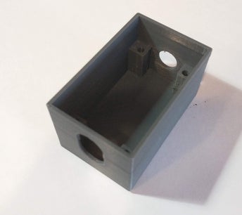
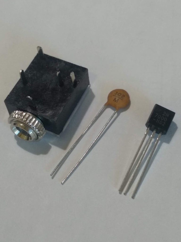
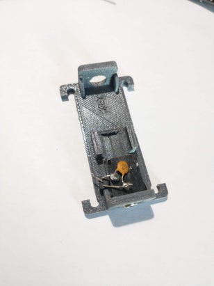
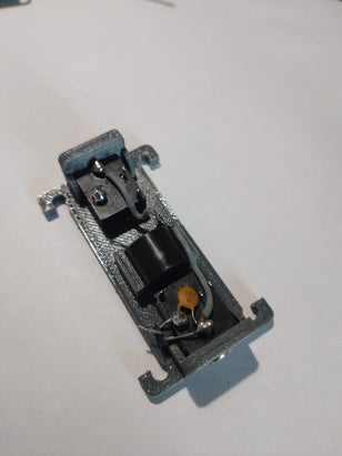
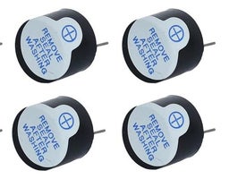
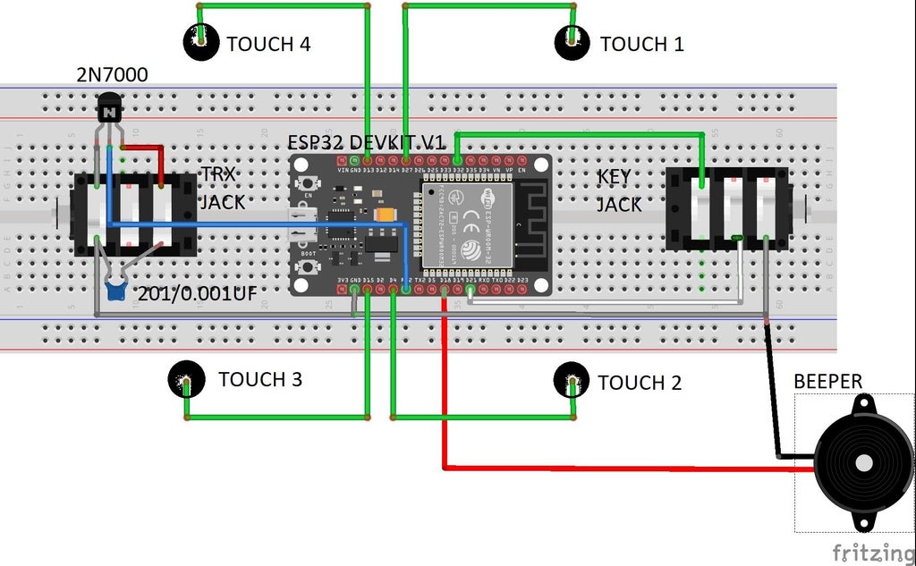
We are going to mount the two 3,5mm stereo jack, the 2n7000 transistor and the beeper.
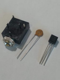
In picture 1 we can see the 3,5mm jack, the 0,001uf(102) capacitor and the 2n7000 transistor.
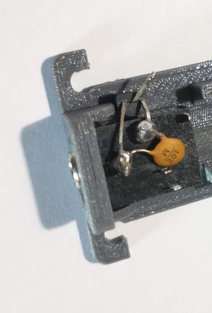
Install the jack on the transceiver place. Now we can weld the transistor and the capacitor to its terminals.Pay attention to the correct orientation of the transistor. In the picture , it is easy to see it.
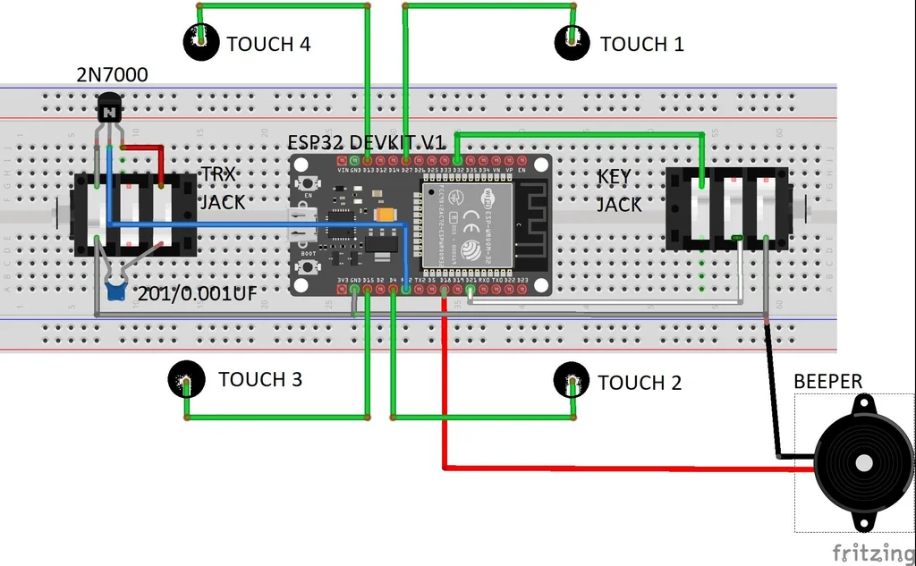
Now we can install the beeper and the second jack. We have to connect the terminals of the jacks and the (-) terminal of the beeper. They will be connect to grd of the esp32.
Step 3: WIRING THE ESP32
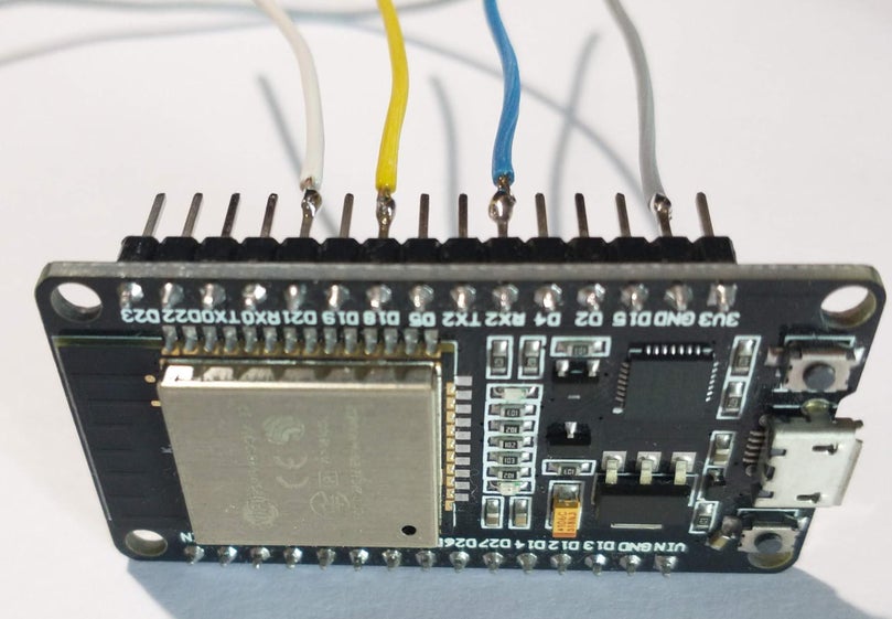
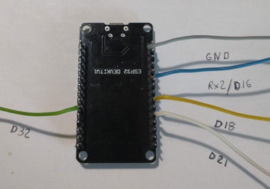
Weld a 5cm long wire on gpio 21 , 18 , 16(rx2) and GND. 5cm are not necessary but we will cut the spare wire.
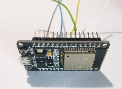
weld a 5cm long wire on gpio 32.
on the last picture you can see the complete set of wires .
Step 4: MOUNTING THE ESP32
Place the esp32 the way showed in picture 1. Notice that one of the sides of the holder is marked USB on the bottom .
I mount the tap and the screws in order to ease the operation. It is provisional.
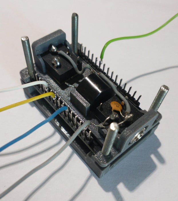
Wire d21 and d32 to the key jack the way shown in picture 2.
Wire GND to the center point of the jack (grey)
Wire D16/rx2 to the central terminal of the 2n7000.
Wire D18 to (+) of the beeper.
Step 5: WIRING THE TOUCH SENSORS
This step is useful only if you want to have touch buttons in the keyer.
It is not essential because the keyer is also bluetooth controlled.
My advice is using this feature . It makes the keyer more functional.
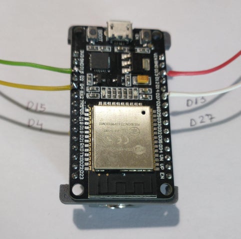
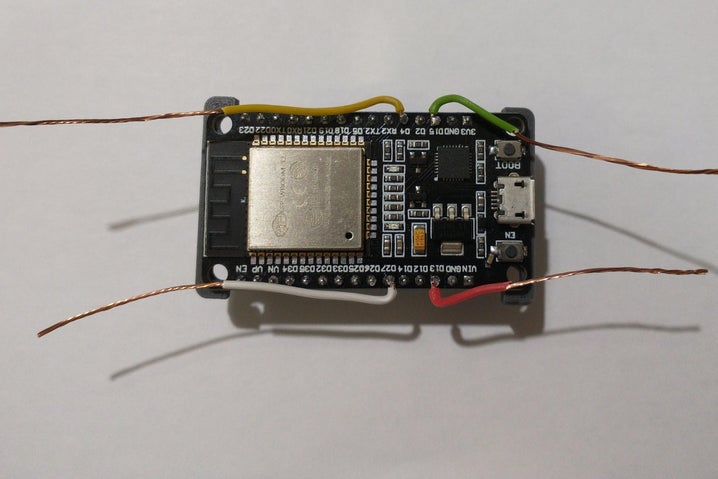
Weld four 5cm long wires to D15 , D4 , D27 and D13.
Peel the wires like in picture 2. Remove the cover until the holes.
It is because every wire is joined with the screw in line with the holes.
The length of the wires is critical. The shorter the wires the more precise the touch.
In case you decided to install the esp32 in a different case than this 3d printed one, try to install the wires as short as possible. Longer wires could trigger touch buttons without touching them.
In any case, you can adjust sensitivity from 0 ( no touch) to 90 ( very sensitive). Factory default is 40.
Step 6: MOUNTING THE TAP AND TOUCH BUTTONS
One of the most interesting features of this design is the touch control.
To simplify the design I take the most of the four screws that lock the case.
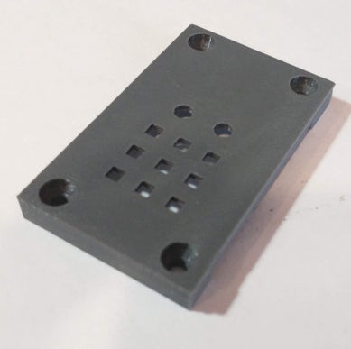
In order to join the screws and the wires I have prepared four small holes as you can see in picture 1. They are perpendicular to the ones devoted to the screws. These holes are 2mm diameter so the printing must be 0,125 layer height.
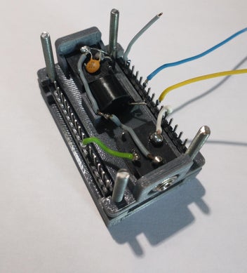
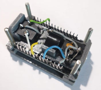
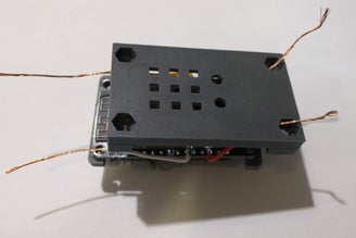
Pass the wires through the holes as you can see in pictures 2 and 3.
Once the wires were passed,tight them.Now you can mount the rest of the case
Step 7: FINISH THE ASSEMBLING

Once the package is assembled, introduce the screws in their holes.
Cut the wires as you can see in picture 2.
Surround the screw with the wire, Hide the wire like in picture 3.
Screw the nuts so they keep touching the wires.
Now the box is locked, You can notice that the head of the screw emerges from the box. This is for making the touch easier.
Step 8: COMPONENTS
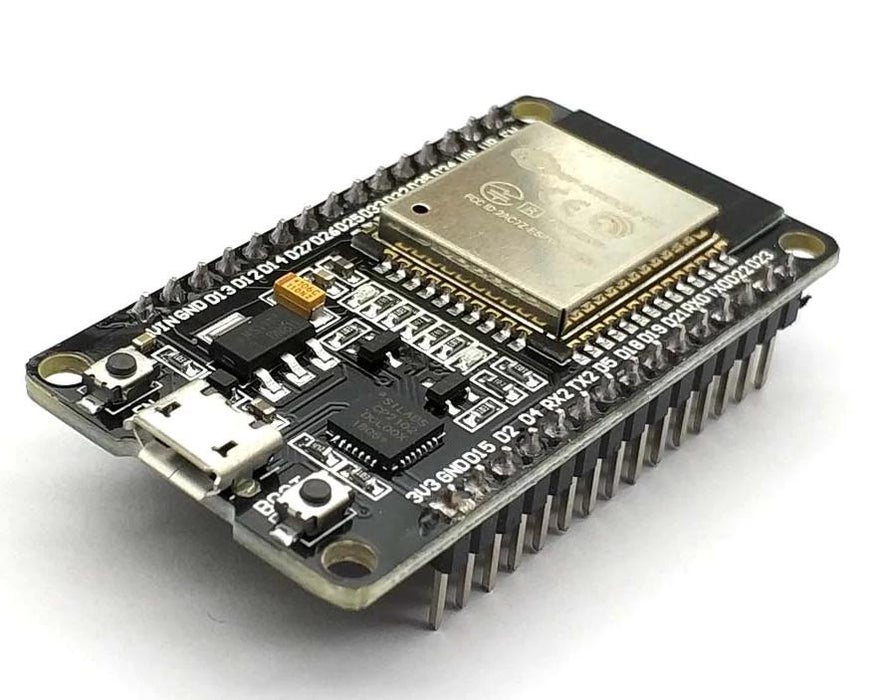
ESP32 DEVKIT V1 (SOLDERED KIT) (1 UNIT)
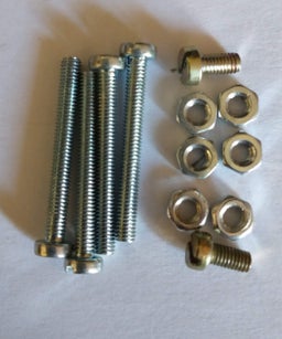
FOUR SCREWS M3 x 30mm WITH ITS NUTS
0,001UF CERAMIC CAPACITOR
Step 9: INSTRUCTIONS AND SCHEMATIC
Bluetooth instructions descrives how to configure the app BlueTooth Serial Controller :
You have also a video with this instructions,
In general instructions you have the instructions to use the keyer.
28/04/2024
The app is temporary unavailable so you can use a variation from the same author.
Bletooth serial 16 buttons . It is the same but with less buttons .
18/05/2024
Thanks to EA3KR that found the apk in Softonic :
Attachments
Step 10: CODE
This project is ESP32 based. Yu need to install this card in the arduino IDE to load the code to your ESP32.
In this page you’ll find how to install the card:
Installing the ESP32 Board in Arduino IDE
This project uses a DOIT ESP32 DEVKIT V1 card but you have to select ESP32.DEV.module in the board manager.
It is essential to install the library BluetoothSerial.h
It is included in the ESP32 master
Download and unzip ESP32_master and, inside it, there is a folder containing all the libraries you’ll need:
1)-BluetoothSerial to serial communication with your mobile
2)-WiFi it is used only to save energy
3)-EEPROM to store messages and parameters
I have added a file with the three libraries you need.
Here you can learn how to install libraries in arduino IDE
All the libraries you need are on ESP32_MASTER
How To Include Zip File Librarys To Arduino Software
Attachments
Step 11: Troubleshooting
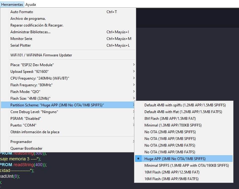
-1) Sketch is too big….
If you see this message in the Arduino IDE, you must configure the card as you can see in the image.

